Scope
This specification describes of 12.1/12.65 KV, 50HZ Pole- mounted automatically
switched capacitor banks of 150 kvar with multi layer arrangement upto 300 Kvar rating with all
accessories & allied components (like CT, PT, fuse, vacuum switches with control box, structures,
clamps & connectors, earth flat, control cable etc.), providing a central monitoring system through
Remote Sensing arrangement and Web Portal based client to WBSEDCL for monitoring the same
including protection system and guaranteeing improvement of average monthly power factor to
level of 0.95 and above in selected 11 KV overhead feeders in different district of West Bengal
under WBSEDCL area.
2.0 Service Conditions :
a) Maximum Ambient Temperature (° C) : + 50°C
b) Minimum Ambient Temperature (° C) : + 4°C
c) Max. & Min Relative Humidity (%) : 100 & 50
d) Maximum annual rain fall (mm) : 2000
e) Maximum Wind Pressure (Kg/m sq) : 150
f) Maximum wind velocity (m/sec) :50
g) Isoceraunic Level (days/year) : 200
h) Maximum altitude above mean sea level (Meter) : 1000
i) Seismic Level ( Horizontal acceleration) : 0.3 g
3.0 Operating conditions :
a) Nominal System Voltage : 11 KV
b) Highest System Voltage : 12 KV
c) Normal frequency : 50 Hz
d) No. of phases : 3
e) System fault current : 18.4 KA for 3.0 sec
4.0 Applicable Standards :
Unless otherwise stipulated in the specification, the 12.1/12.65 KV pole mounted
automatically switched capacitors shall be comply with the latest version of IS: 9920 for
automatic capacitor Switch and IS:13925 (Part-I) for Pole mounted Capacitor Bank.
5.0 Basic Requirements:
5.1 The bidder shall conduct survey, measure and submit voltage and power factor of
the selected 11KV feeder at the at Sub-Stn end and the extreme tail end and
different critical load points of the feeder.
5.2 The bidder shall submit design for installation of multi switching capacitor banks of
150kvar each for guaranteeing improvement of average monthly power Factor to a
level of 0.95 and above
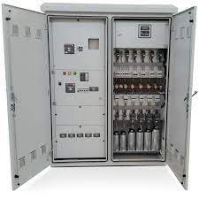
5.3 The capacitor banks are to be automatically operated.
5.4. The bidder shall provide a central monitoring system through Remote sensing
arrangement of their own and Web Portal based client to WBSEDCL for monitoring
the same.
5.5 Permissible over load:
The maximum permissible overloads with regard to voltage, current and reactive
Output shall conform to IS:13925
5.6 Power loss:
The power loss in capacitors shall not exceed 0.2 Watt/kvar
5.7 Discharge Device:
Suitable discharge device shall be connected across the capacitor units in
accordance with the provision of IS:13925. The discharge device shall reduce the
residual voltage from the cross value of the rated voltage to 75 Volt or less within
10 minutes after the capacitor is disconnected from the source of supply.
5.8 Earth Connection:
The container of each capacitor units shall be provided with suitable earthing
terminal.
5.9 Protective Fuses:
The capacitors shall be provided with external fuses. It shall be possible to identify
the blown off fuse from the outside. The tolerance and the degree of unbalances
shall also be indicated as per relevant IS. The manufacturer shall supply a set of
external fuses together with fixing accessories and a set of three spare fuse links
along with capacitor bank.
6.0 General requirements :
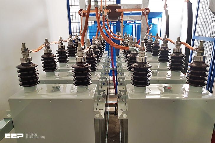
6.1 The Capacitors shall be of non PCB Type, using polypropylene film as the dielectric.
6.2 The containers shall be made from sheet steel of thickness not less than 1.6mm.
6.3 The Container shall be hermetically sealed by controlled arc welding process.
6.4 The fuse and capacitors cells shall be interchangeable.
6.5 The dielectric loss angles (tan delta) shall be less than as per relevant IS
A. 11 KV Automatic Capacitor Switches
1.0 RATED CURRENT:
The standard rated normal current shall be 200 A.
2.0 RATED CAPACITIVE SWITCHING CURRENT:
The rated capacitive switching current shall not be less than 50 A.
3.0 i) RATED SHORT-TIME CURRENT:
The rated short-time symmetrical current for 1 second shall be 4.5 KA.
ii) RATED MAKING CURRENT:
The rated making current shall be 6 KA and above.
4.0 BASIC IMPULSE LEVEL (BIL):
The rated basic impulse level of switch to earth as also across the open terminals shall
be 75 KV.
5.0 CONTROL SUPPLY:
The capacitor switch shall be self-powered from the 11KV line, i.e., no AC or DC control
supply shall be required to be provided by the Utility for its operation. The source
of control supply (auxiliary transformer, etc.) should work satisfactorily with
voltage fluctuations on the 11KV line from (+) 10% to (-) 20%.
6.0 DESIGN AND CONSTRUCTION REQUIREMENTS:
1. The capacitor switches may be of either single-phase or three-phase
construction as per standard design of the manufacturer.
2. The switch shall be of either vacuum or SF6 type.
3. The capacitor switch shall be suitable for outdoor installation and shall have
sealed weatherproof type construction.
4. The capacitor switch shall be provided with a mechanical indicator to show the
contact position in open/closed position.
5. The metallic enclosure of the capacitor switch shall be provided with two earthing
terminals (marked with the earth symbol).
6. The bushings provided on the switch shall be of high quality porcelain and shall
have clamp type of terminal to directly receive aluminium conductors up to
10mm dia in both horizontal and vertical directions. The terminal
arrangement shall be such as to avoid bimetallic corrosion.
7. The switch shall be provided with suitable structures for mounting with capacitor
and control parameter on the double pole structure
8. All nuts, bolts and mounting structure shall be hot dip galvanized.


Reviews
There are no reviews yet.